Computer Controlled Cutting
Week 3 assignment:
-
Group Assignment:click here.
- Characterize laser cutter’s: Focus, Power, Speed, Rate, Kerf, Joint clearance, and types
-
Individual Assignment:
- Cut something on the vinyl cutter
- Design, laser-cut, and document a parametric construction kit:
Vinyl Cutting
Vinyl cutting presents an intriguing process whereby 2D images or vectors are precisely carved into vinyl using a computer-controlled CNC machine equipped with a maneuverable pen knife.
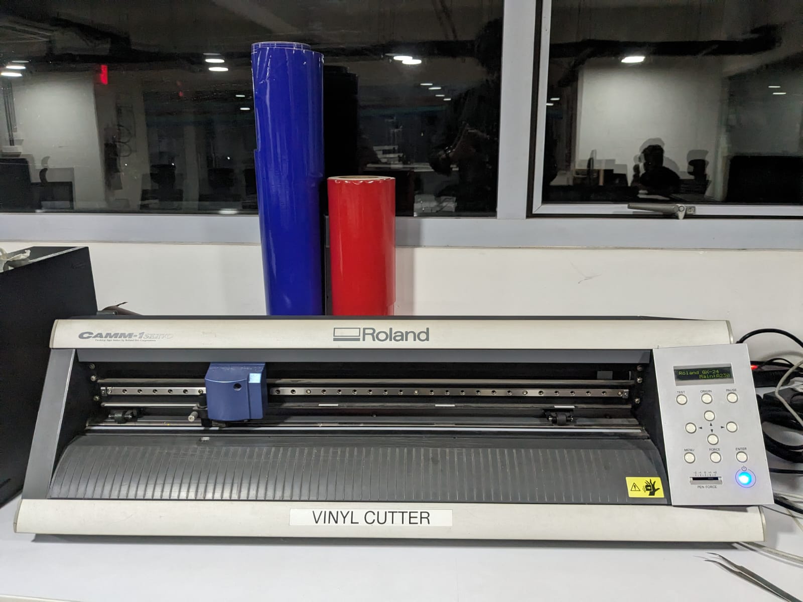
ROLAND GX-24
The Roland GX-24 is a desktop vinyl cutter widely used in the sign-making and apparel decoration industries. It's known for its precision cutting capabilities and versatility in handling various types of vinyl materials. With its computer-controlled operation, it can accurately cut intricate designs and shapes from digital files. The GX-24 is often used for creating vinyl decals, signage, heat transfer graphics for garments, and more.
This is the type of vinyl-cutting machine utilized in our lab.
When discussing vinyl cutting machines, there are primarily two types available:
Active and Passive.
In active machines, the cutting blade's rotations are controlled by a servo mechanism. However, in passive machines, the turning mechanism resembles that of a roller coaster tire. If the entire head moves across a plane, the blade will turn in that direction. The Roland GX-24 is a passive blade-type machine.
It operates on a servo motor, providing high-speed precision. The blades are sharply pointed, angled at 45 degrees to the cutting direction, as depicted in the image. Additionally, blades with cutting angles of 30° and 60° are available.
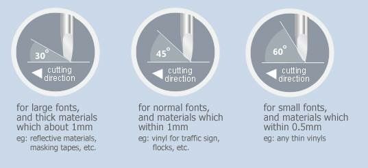
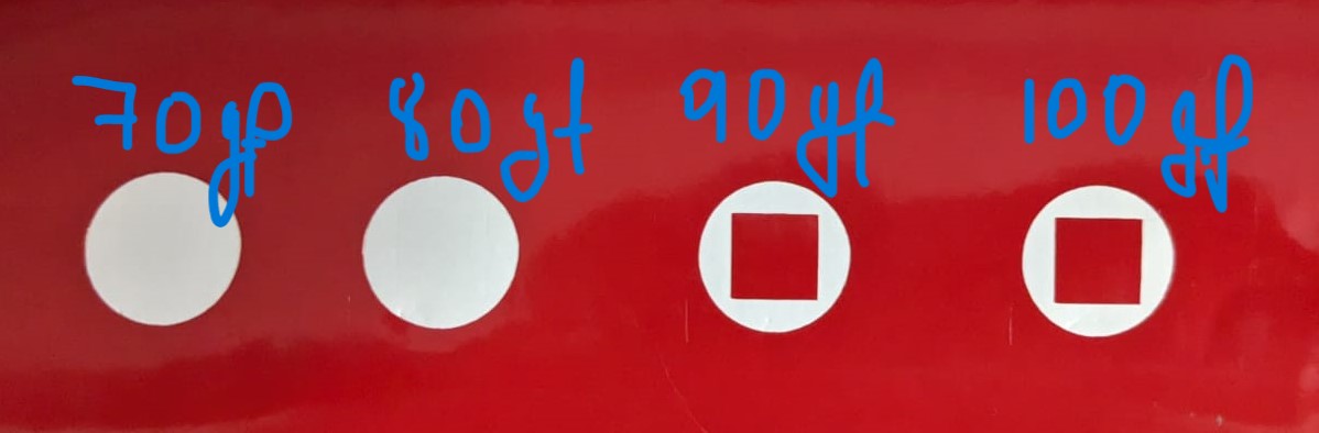
In our lab, we use 45° cutting angle blades. The cutting speed depends on the force applied in the machine and the surface quality of the material being cut. Excessive force can damage the vinyl and the cutter tool. Therefore, we conducted a force test on the vinyl stickers from our lab's inventory.
The successful test involves removing the circular shape without damaging the inner square shape, as shown in the figure. In the figure, there are different tests conducted with varying forces. From the results, it was determined that 90gf is the optimal force for cutting this material.
The Roland cutting specifications are as follows:
Force: 80 gf
Speed: 20cm/s
The force may need to be adjusted if the speed is increased, as this may result in uncut edges or overcuts at times. These speed and force adjustments can be made in the machine menu, and there is also a button for conducting test cuts.
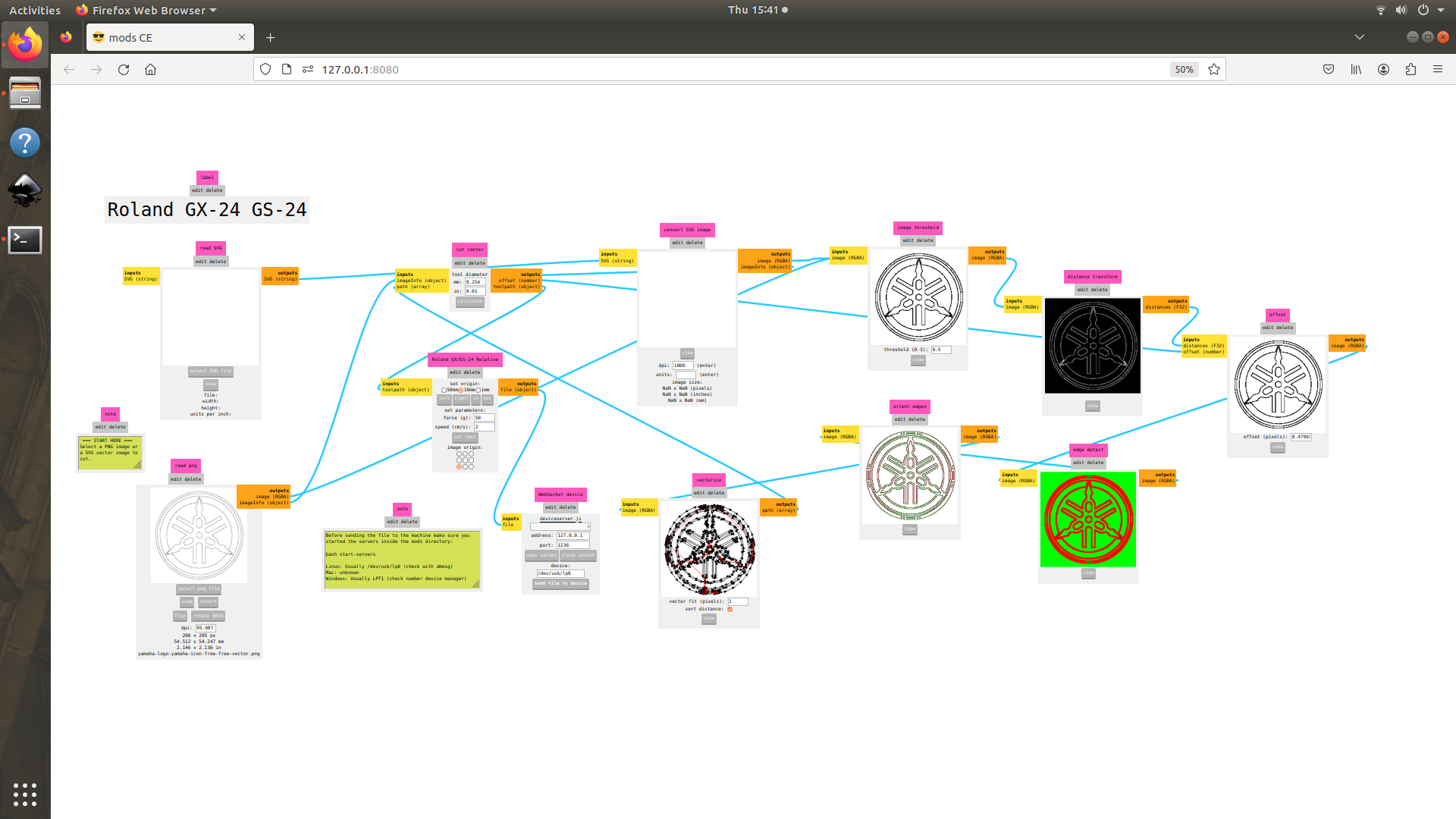
FAB MODS
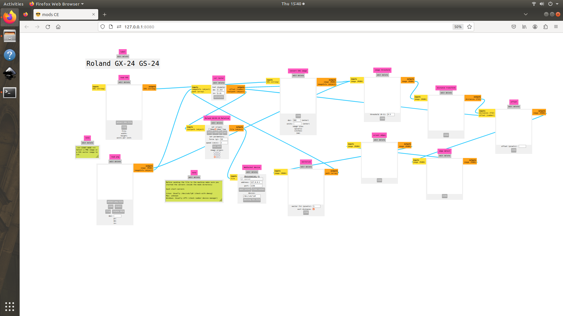
Fabmods is an open-source web app program designed to function as machine software or drivers, leveraging web socket technology. These mods serve as replacements for window software on machines, enabling manufacturers to cut or mill given image or vector files. Prof. Neil recommended trying out FAB MODS. I attempted to cut vinyl using the FAB cutting machine, specifically the Roland GX-24.
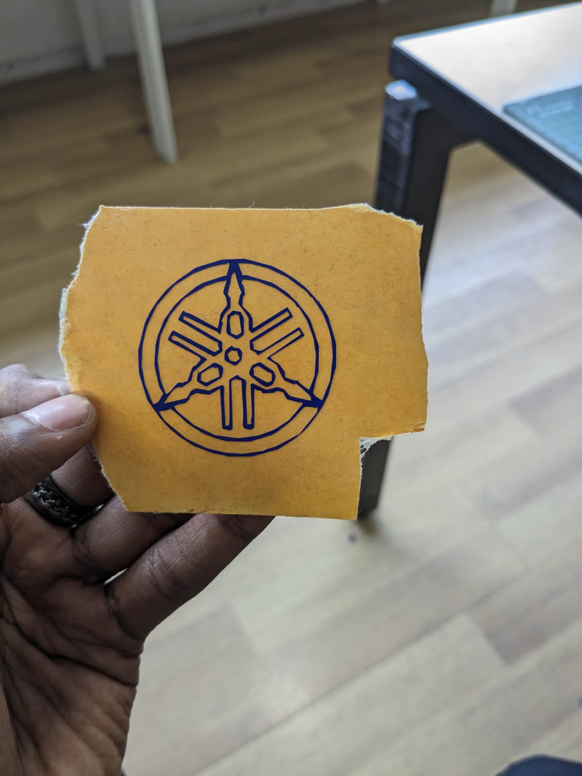
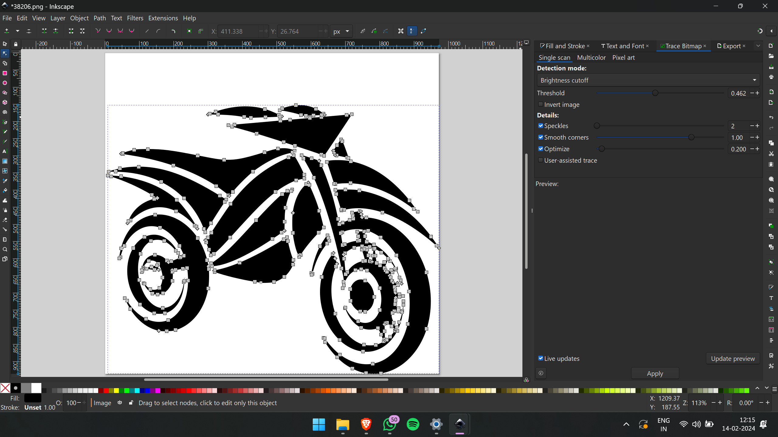
I initiated the process by acquiring the Yamaha logo from the internet. Subsequently, utilizing the Inkscape software, I employed the Trace Bitmap function to vectorize the logo. Following successful vectorization, I exported the logo in plain SVG format
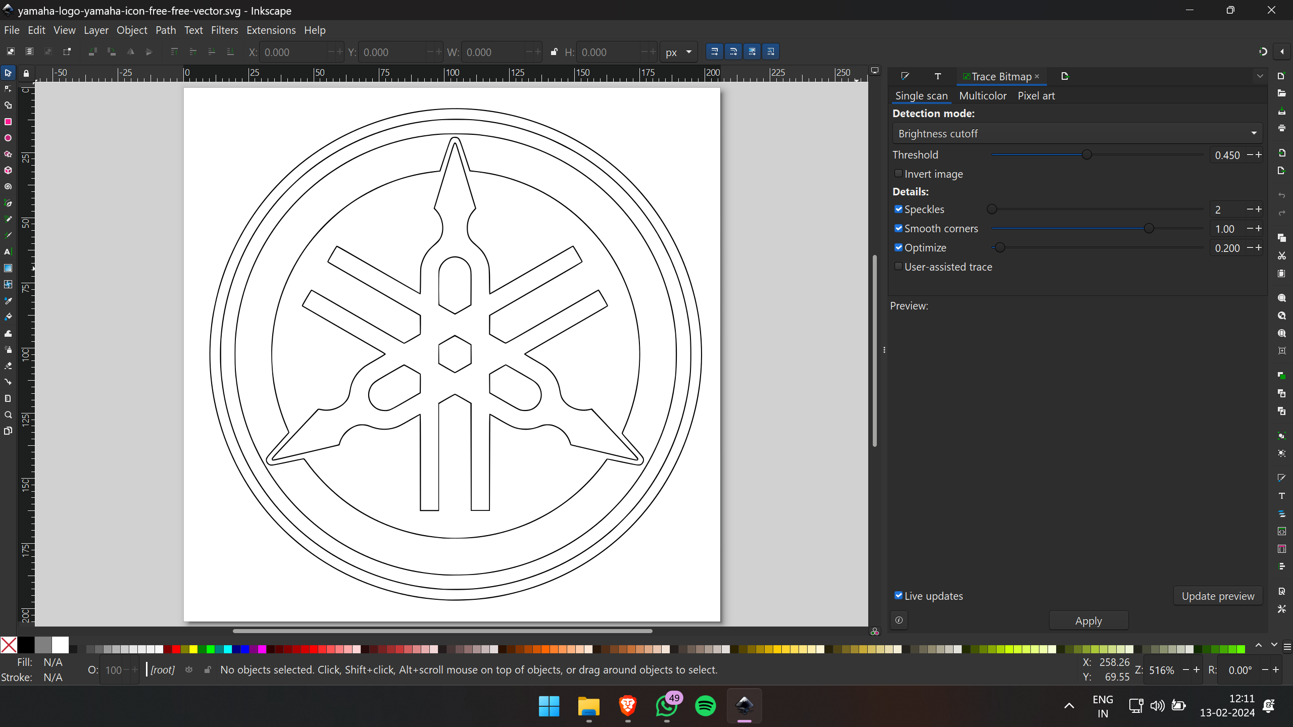
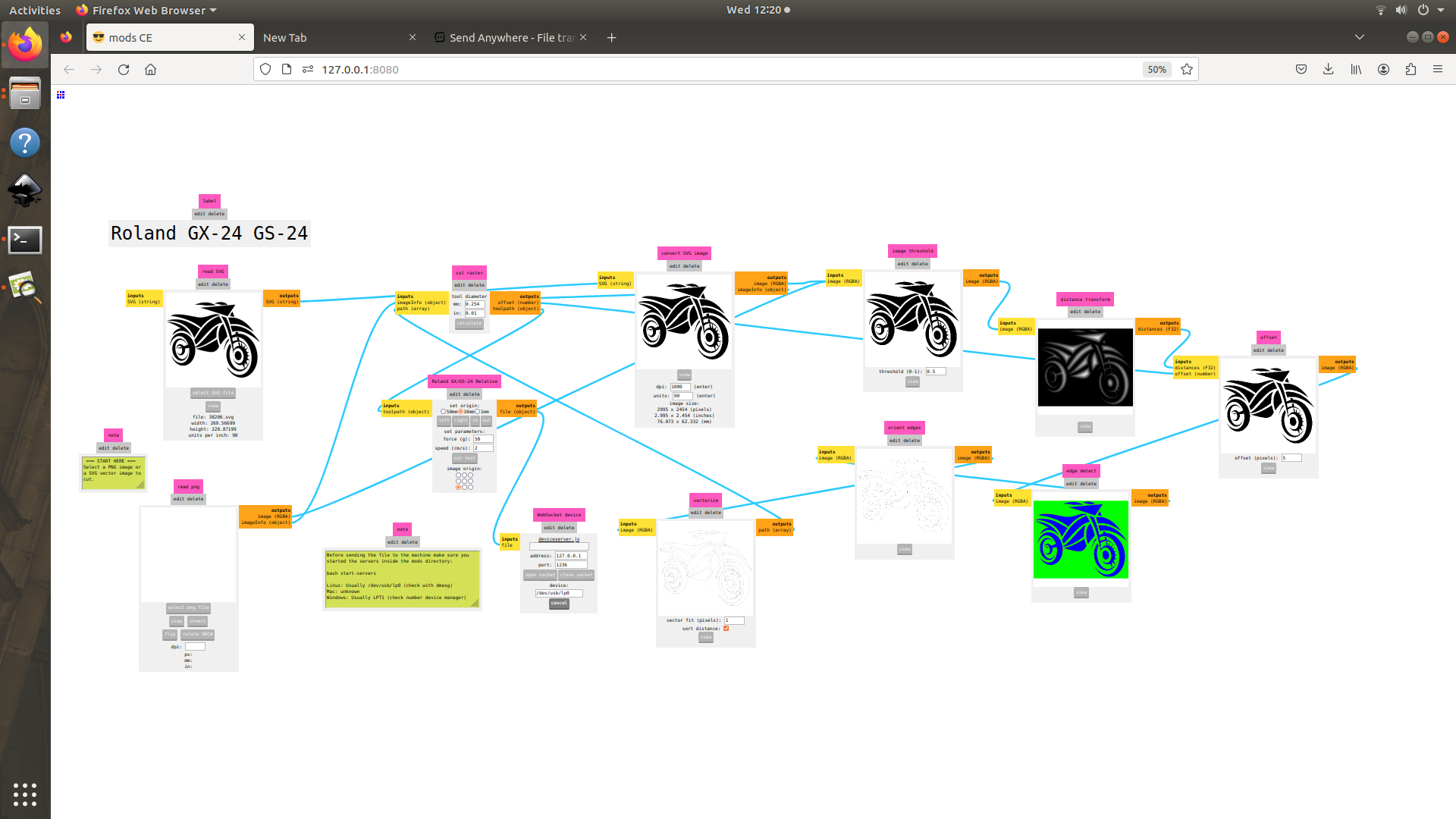
Following the vectorization of the Yamaha logo, I progressed to FabMods, where I uploaded the SVG file. Within FabMods, I ensured a DPI of 1000 and proceeded to calculate the toolpath.
Next, I aligned the vinyl by adjusting the roller guides within the designated white-marked area. It's important to note that the unmarked areas lack the necessary grip to hold or push the vinyl effectively.
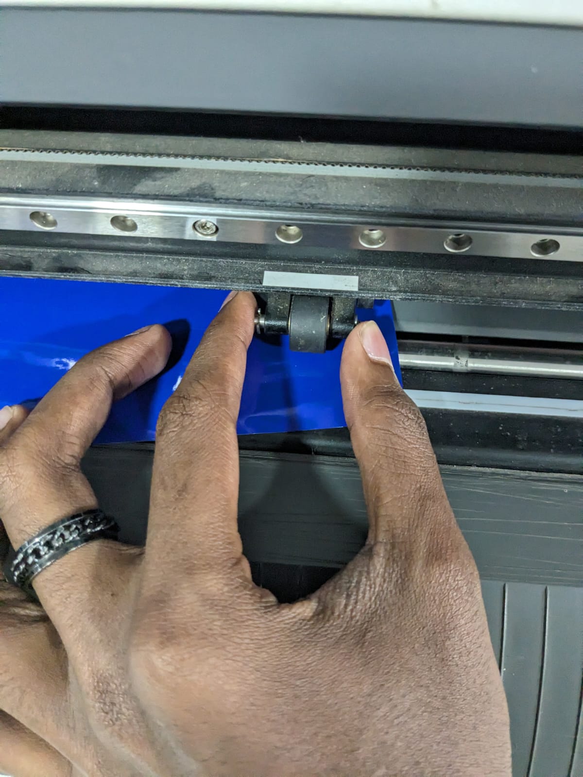
I accessed the "Roll Option" menu to specify the roll type being used. Subsequently, the system automatically measured the length of the vinyl and displayed its dimensions for reference.

Upon confirming the size and toolpath accuracy, I initiated the process by clicking the "Send File to Machine" button, thereby transmitting the file to the vinyl cutter and commencing the cutting operation.
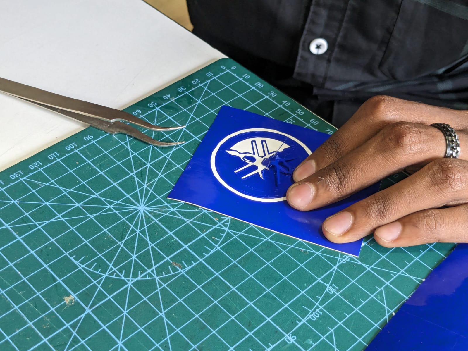
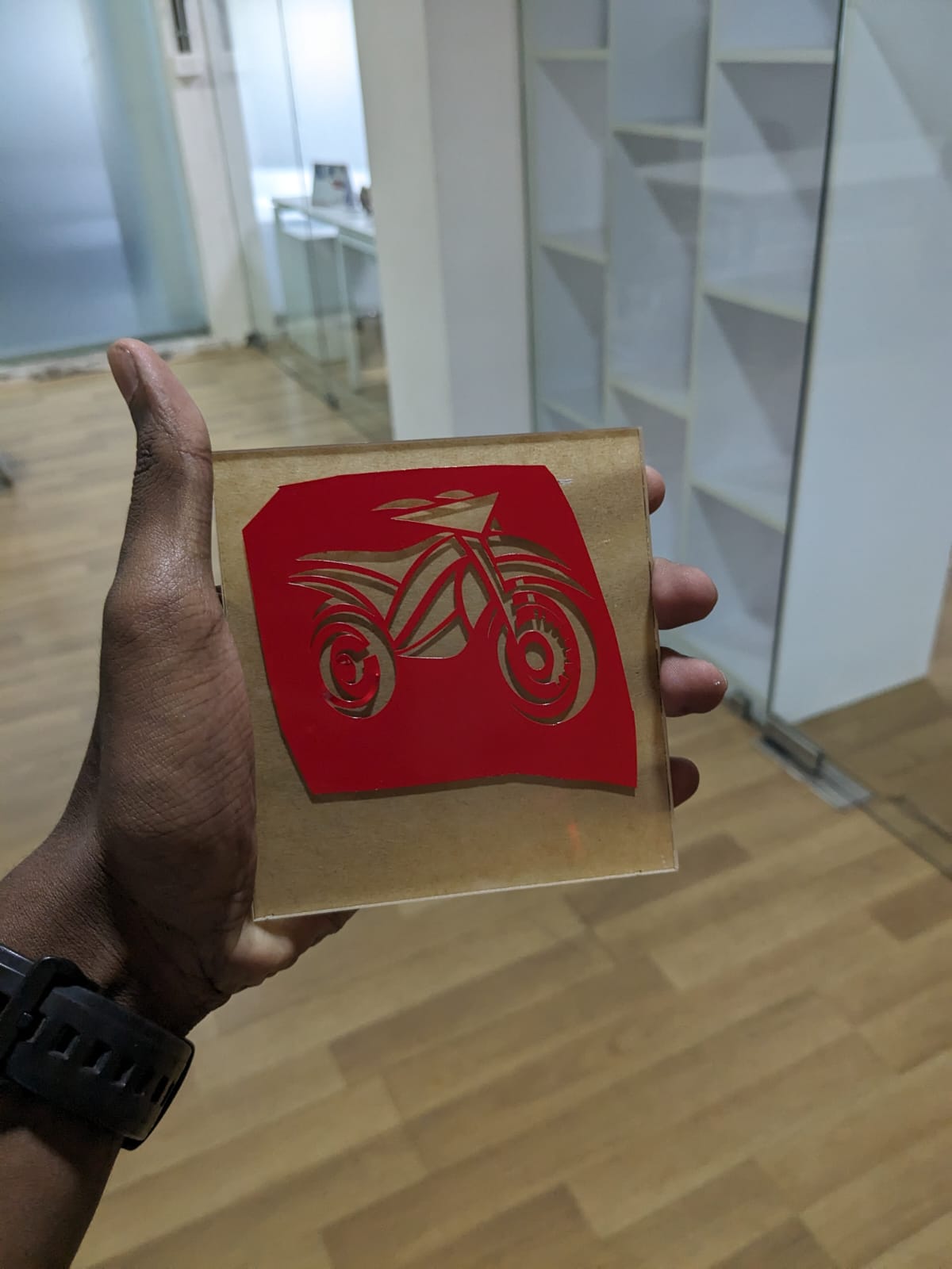
After completing the cutting process, I began removing the negative or unnecessary parts of the vinyl, leaving behind the desired design.
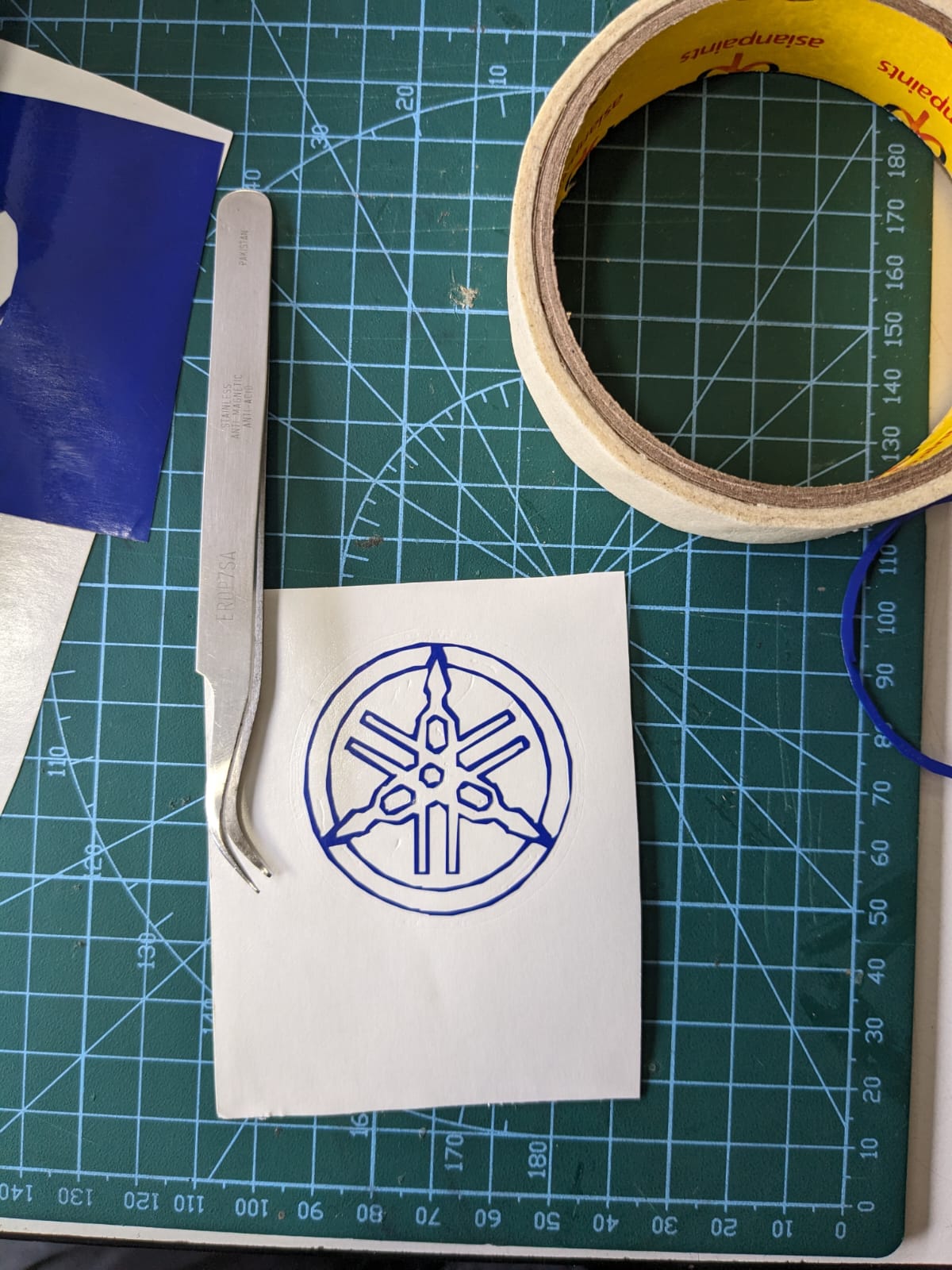
To adhere stickers onto surfaces, it's essential to use a type of tape with low tackiness
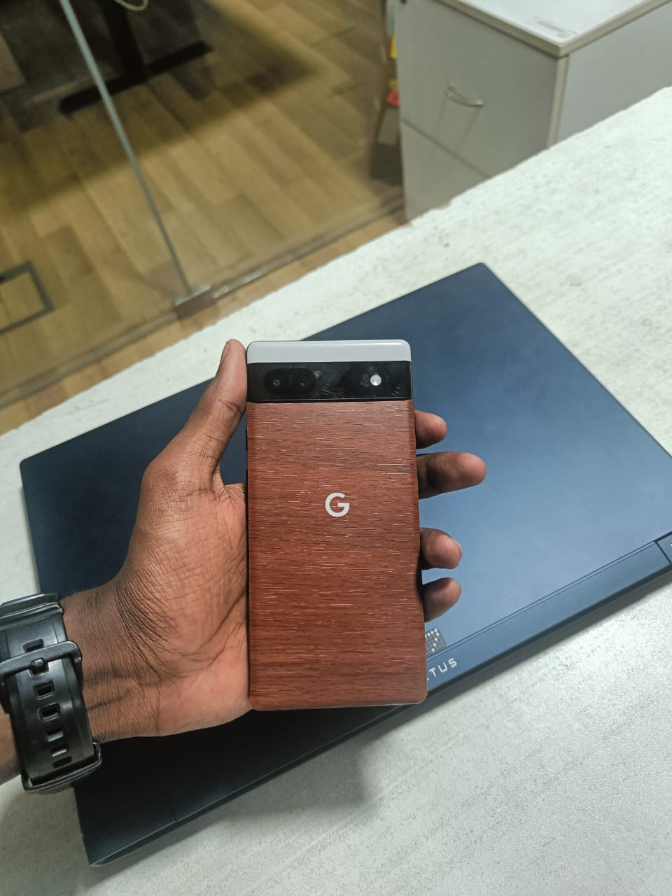
I proceeded to transfer the sticker onto transfer tape and affixed it to the backside of my mobile device.

Next, I intended to undertake a project involving vinyl cutters and a sandblaster. The idea was to utilize the sandblaster to etch a design onto clear acrylic by employing the vinyl as a stencil for the desired pattern.
Initially, I sourced an image from the internet and extracted its vector format using Inkscape software, utilizing the Trace Bitmap tool.
Subsequently, I employed the fab modes to execute the design cutting on the vinyl cutter.
Following that, I extracted the image from the vinyl after it was cut, resulting in the negative portions. These negative portions were then adhered to the clear acrylic, while the remaining areas of the acrylic were covered using masking tape.
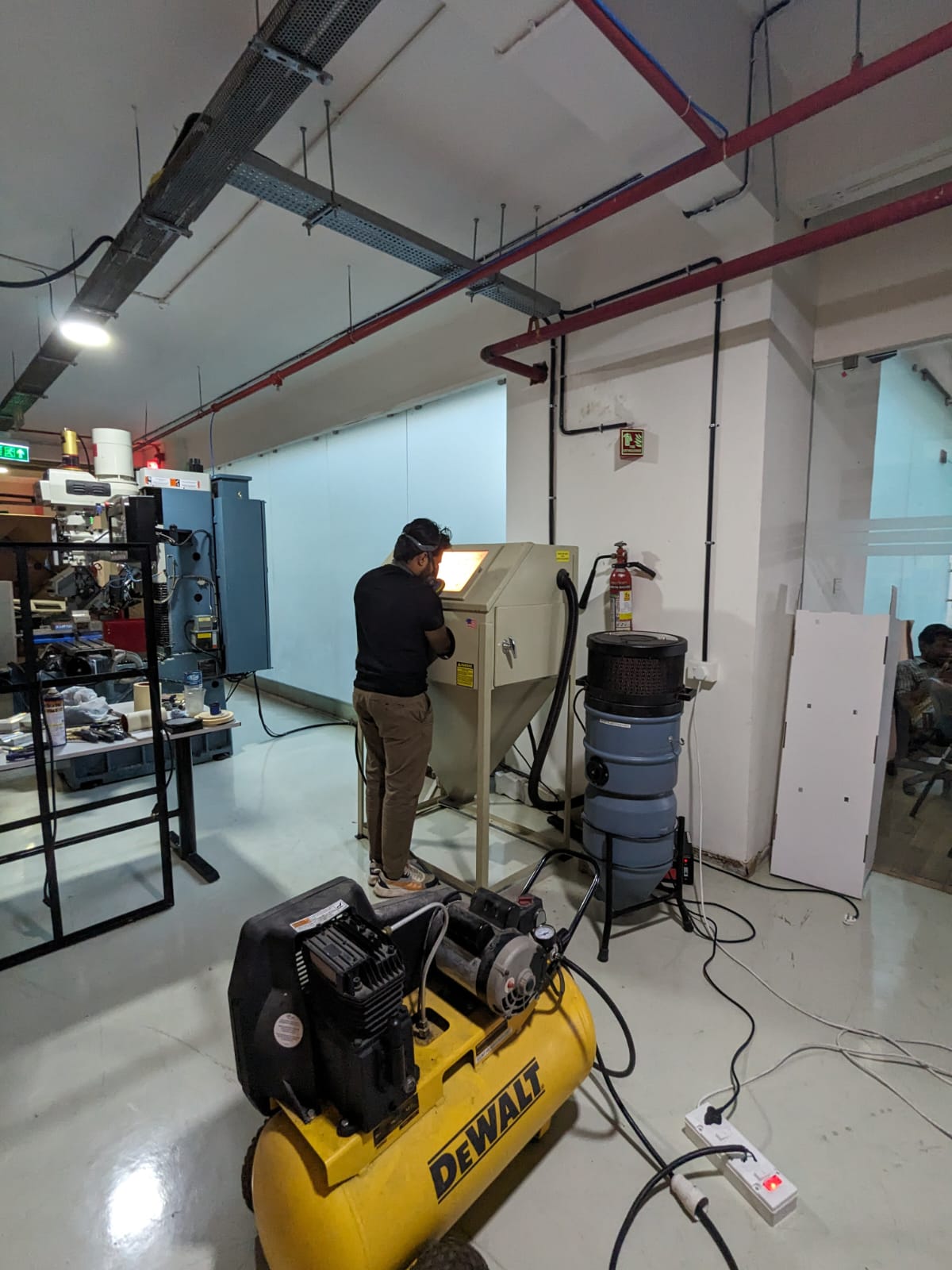
Next, I proceeded to the sandblasting machine located in our lab. Attached is an image of the sandblasting machine for reference
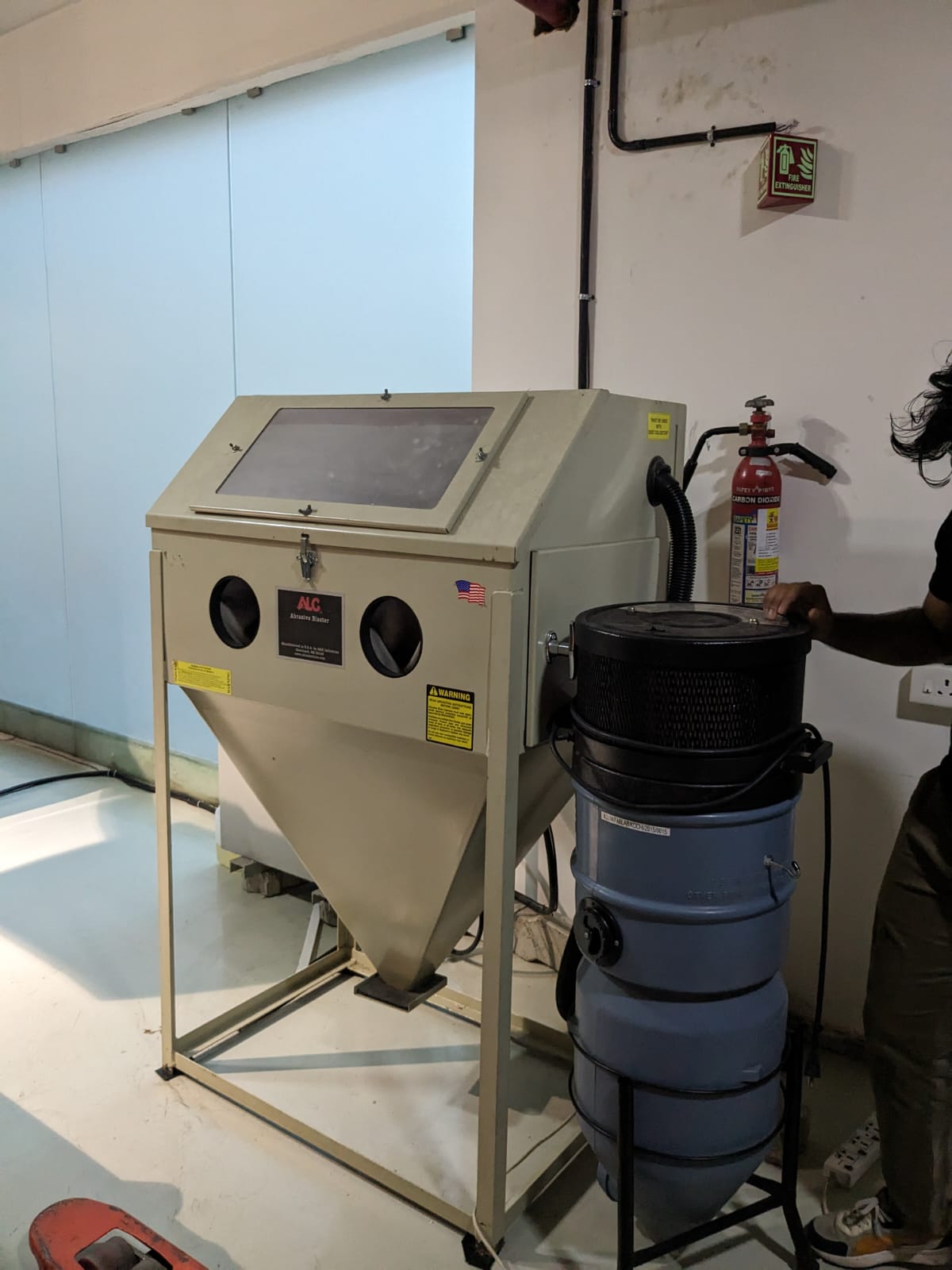
The sandblasting machine in our lab is manufactured by

During the sandblasting operation, it's essential to adhere to necessary safety precautions. For detailed information on these precautions, click here
Subsequently, I initiated the blasting process.
Here is the outcome after sandblasting. Due to insufficient adhesive strength of the vinyl and excessive pressure from the sandblaster, the vinyl stencil peeled off, resulting in damage to the design. This is the result obtained under these conditions.
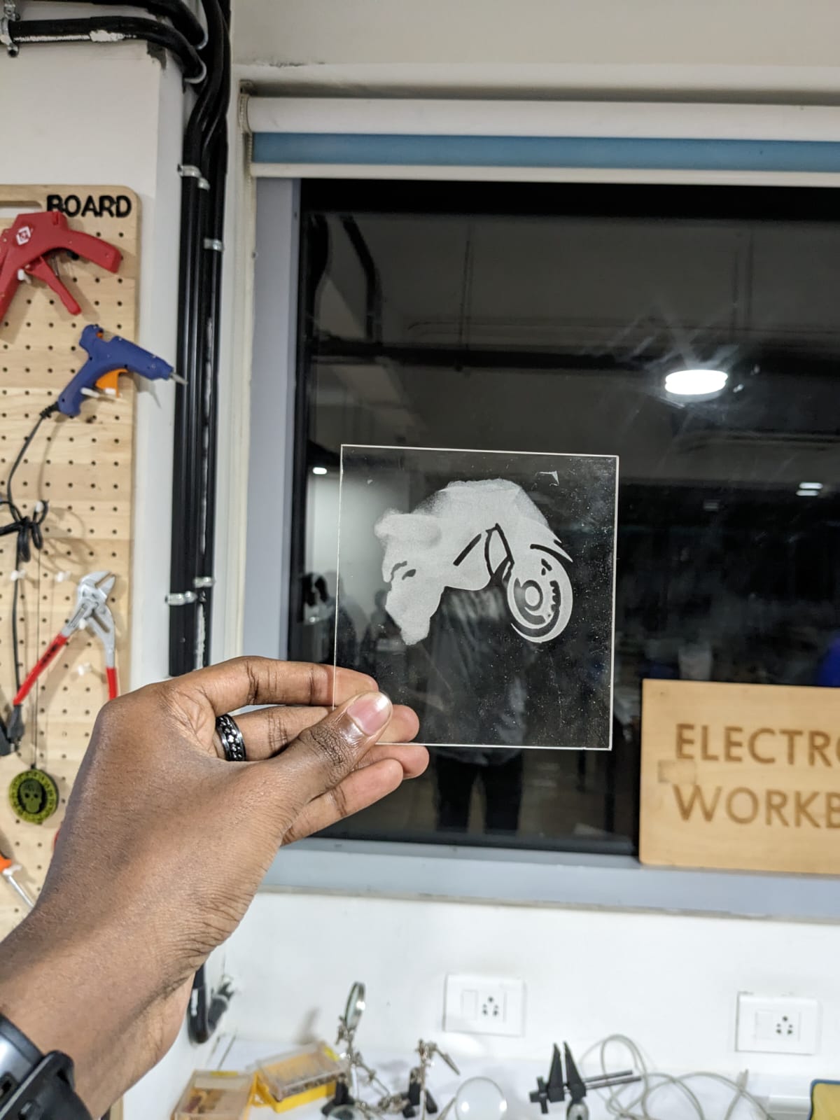
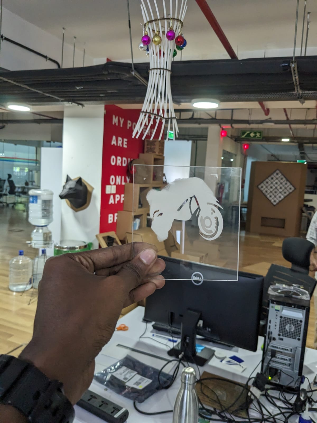
However, by utilizing a vinyl sheet with stronger adhesive properties and maintaining the appropriate pressure, one can achieve a superior outcome.
I also decided to apply vinyl wrap to the backside of my Google Pixel, which is currently in a clear white color, to give it a fresh new appearance.
Before

After
Parametric Construction Kit
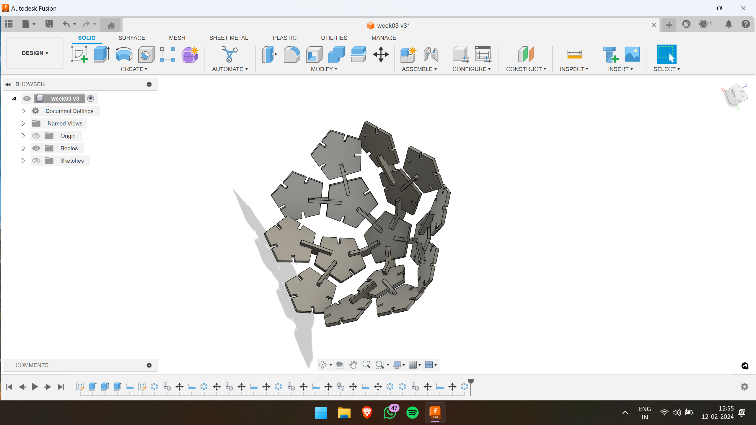
Having utilized Fusion 360 for some time, I ventured into parametric designing for the first time. Leveraging my existing skills, I aimed to craft a press-fit construction piece characterized by simplicity and understated beauty. My goal was to streamline the design to consist of just three pieces, ensuring ease of assembly and an elegant aesthetic.
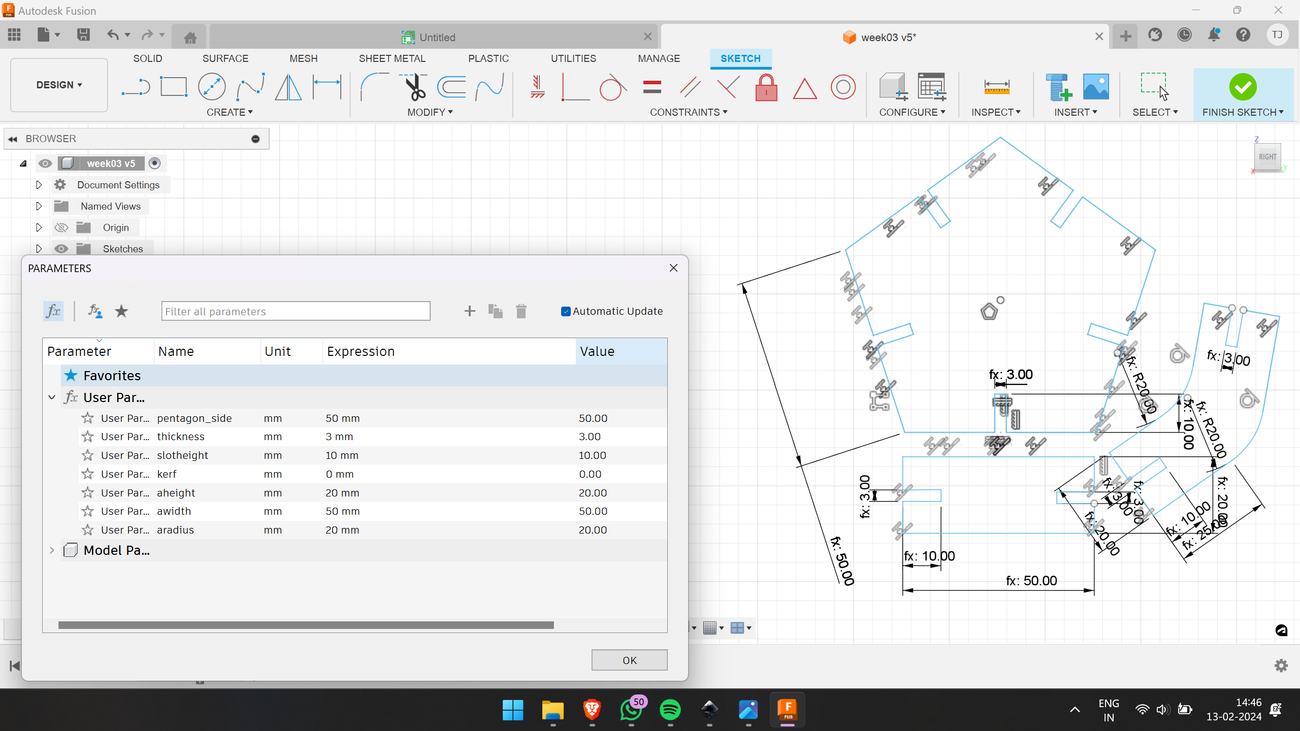
To incorporate parameters, I accessed the Modify menu, then navigated to Change Parameters, followed by clicking on "User Parameter".
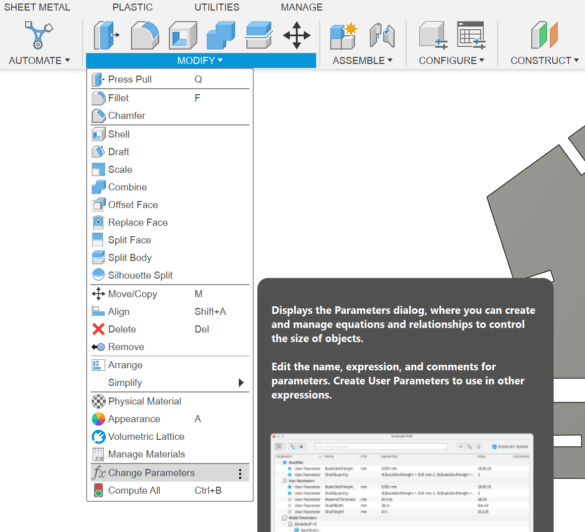
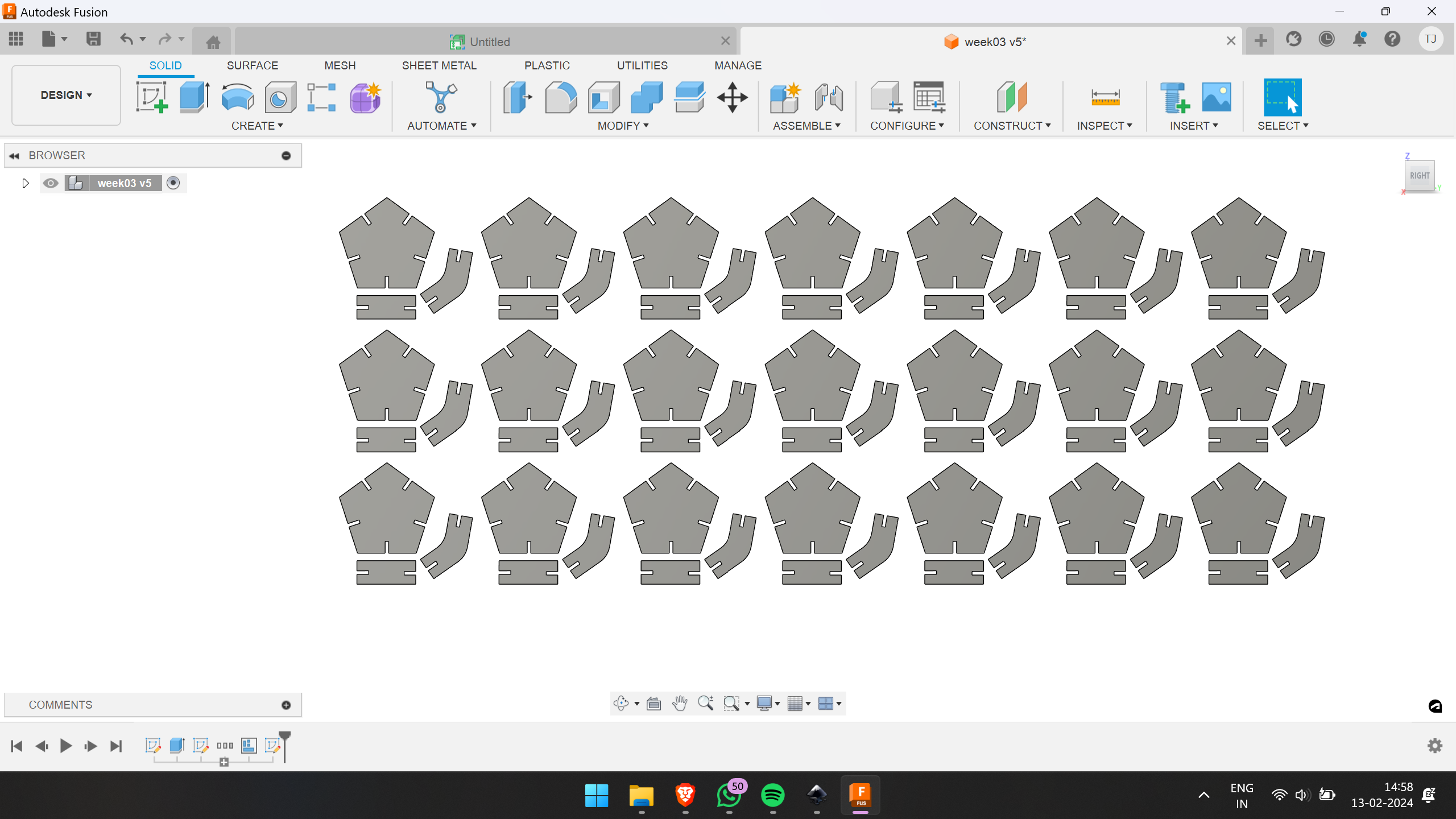
After defining the sketches, I utilized the rectangular pattern feature to multiply them. Then, I extruded the sketches using the parametric value "thickness" to ensure consistency and precision across the design.
I employed the align option to assemble a simple structure. This step allowed me to visualize how the design would appear in its final form, ensuring proper alignment and fit.
or by using the shortcut key
“shift+A”
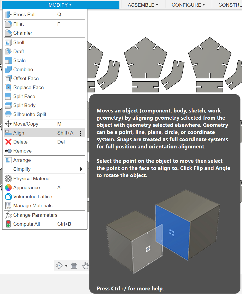
Here is what the assembled structure looks like after utilizing the align option:
To prepare the design for cutting, simply right-click on the sketch and select the "Save as DXF" option. This will generate a DXF file that can be used for laser cutting or other fabrication processes.
The Trotec Speedy 400 Flexx
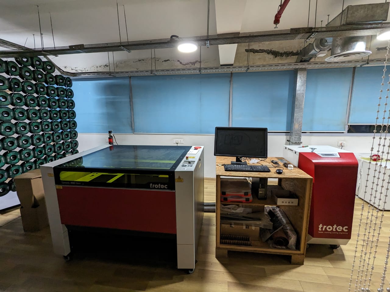
The Trotec Speedy 400 Flexx is a highly versatile laser engraver and cutter renowned for its efficiency, precision, and flexibility. Its unique "Flexx" feature integrates both CO2 and fiber laser sources, eliminating the need for manual switching and enabling seamless processing of diverse materials, including metals, plastics, and organics.
Key Specifications:
- Work Area: Typically offers a spacious work area of approximately 1000 x 610 mm (39.3 x 24.0 inches), accommodating various project sizes.
-
Laser Power:
- CO2 Laser Options: Ranging from 60W to 120W, suitable for cutting, engraving, and marking on materials like wood, glass, acrylic, and leather.
- Fiber Laser Options: Power typically varies between 20W to 50W, ideal for precise marking and engraving on metals and plastics.
- Speed and Productivity: Capable of achieving high-speed operations, with speeds reaching up to 4.3 m/s (169 in/s) and acceleration of 5 g, ensuring rapid and efficient production.
However, due to maintenance issues preventing the laser machine from functioning properly, we had to outsource our laser cutting requirements. For our group assignment, we utilized a laser-cutting machine available at Maker Village. Despite facing constraints in its usage, we completed our group assignment. Additionally, for my assignment, I opted to utilize the ZUND G3 L-2500 Digital Cutter available in FabLab, enabling me to accomplish my tasks effectively.
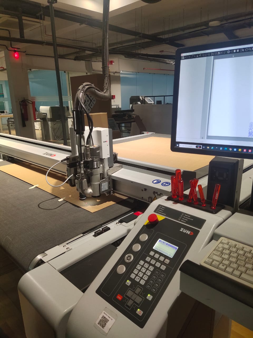
ZUND G3 L-2500 Digital Cutter
The ZUND G3 L-2500 and standard Zund cutting machines are both digital cutting systems utilized across various industries. The ZUND G3 L-2500 excels in cutting, creasing, and routing materials like fabrics, plastics, metals, and composites. Its standout feature is its ability to perform multiple operations within a single process, thanks to its incorporation of different tool modules. On the other hand, standard Zund cutting machines are primarily used for cutting materials such as paper, cardboard, textiles, and plastics.
If you'd like to delve deeper into the capabilities and specifications of Zund cutting machines, click here
To initiate cutting using a DXF file format, begin by opening the cut editor. Then, navigate to File > Add Job and import the file intended for cutting.
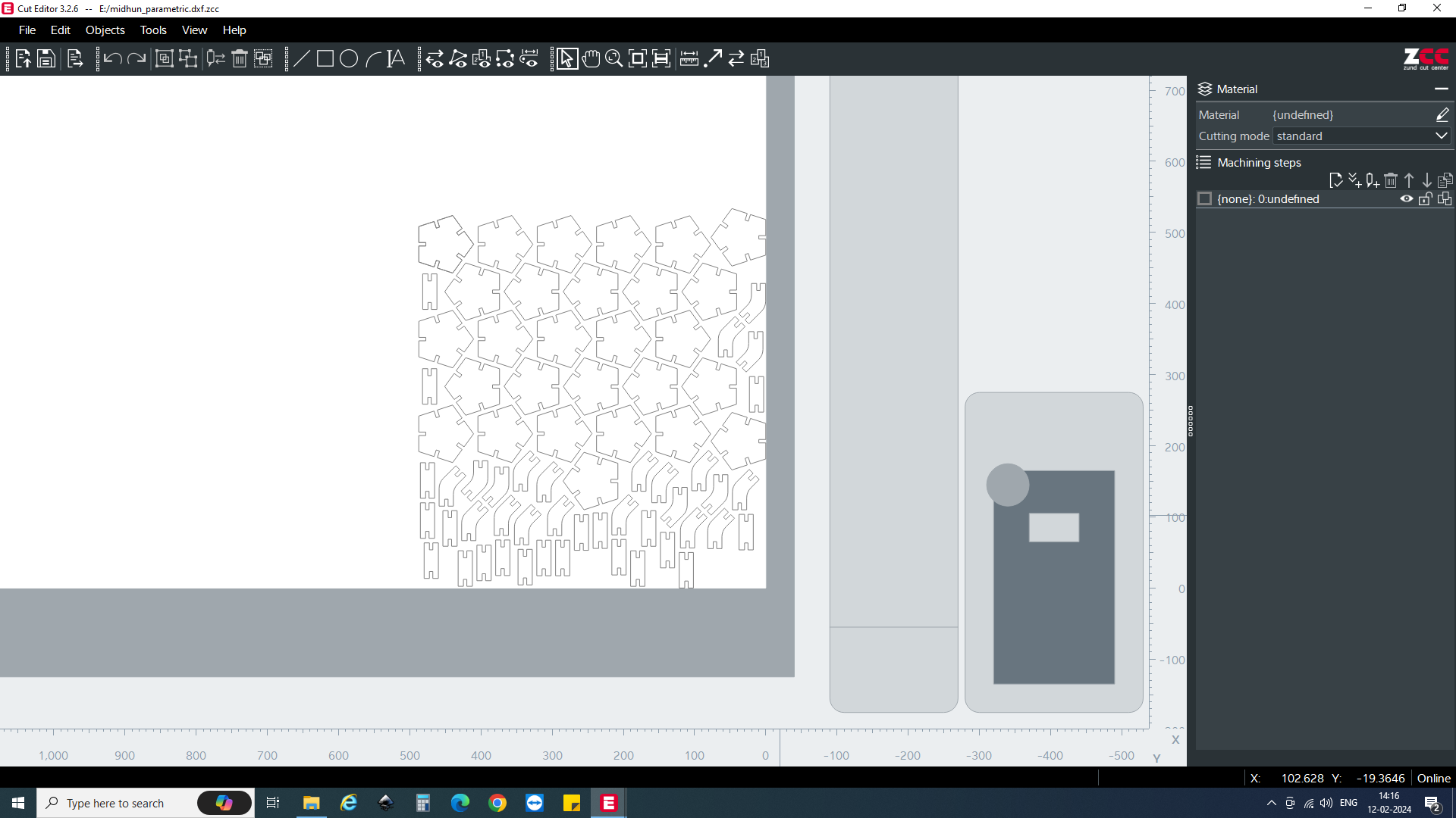
Once the file is loaded, optimize the spacing between individual sketches by pressing the spacebar and adjusting the geometry as needed. Additionally, select all figures and proceed to Objects > Numerical Geometry. Offset the X and Y axis from the origin to establish an initial clearance before commencing the cutting process.

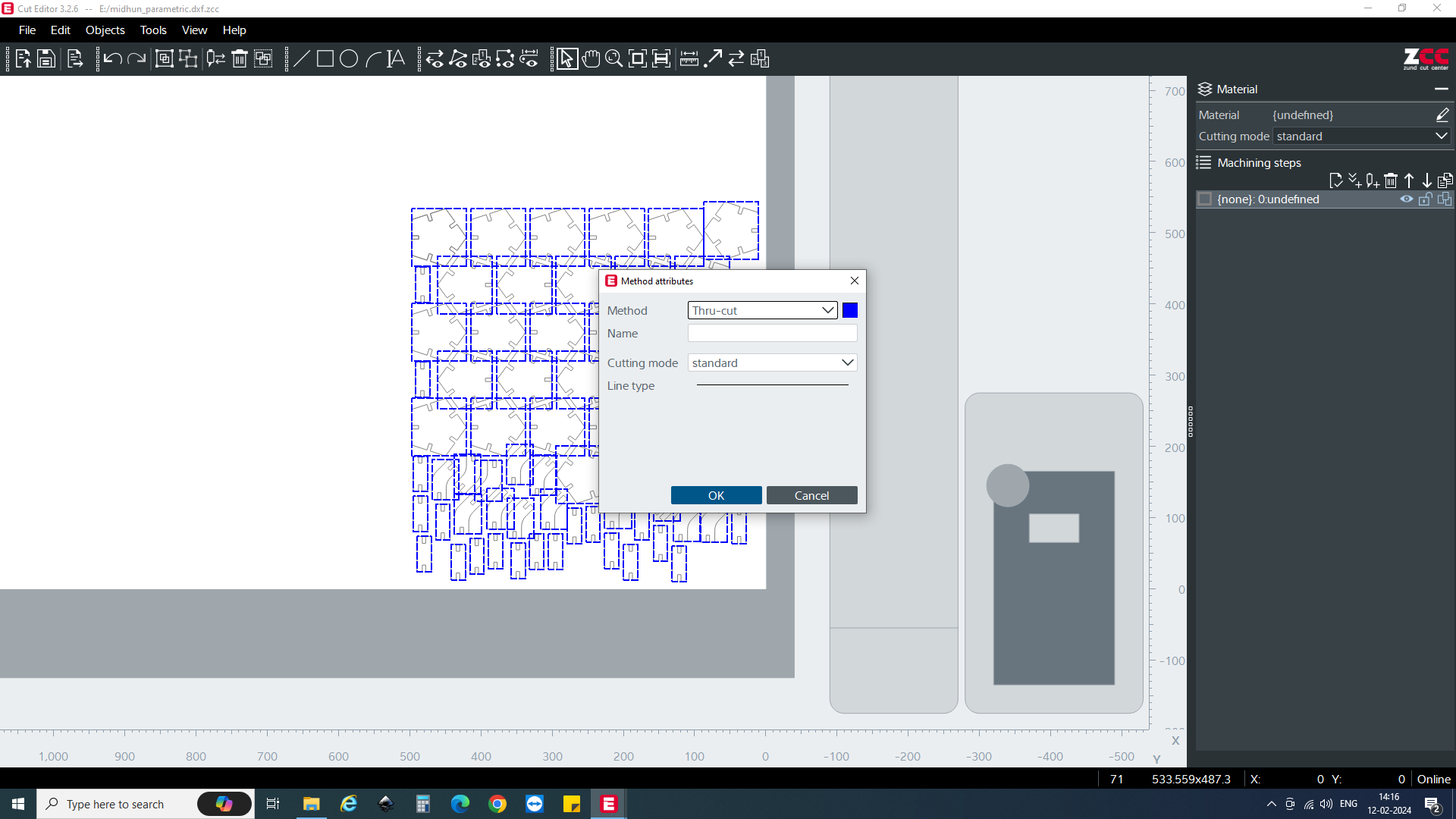
Starting from the rightmost corner of the interface, define the type of operation to be performed. Various operation types are available, including creasing and cutting. Select the specific operation required for the task at hand.
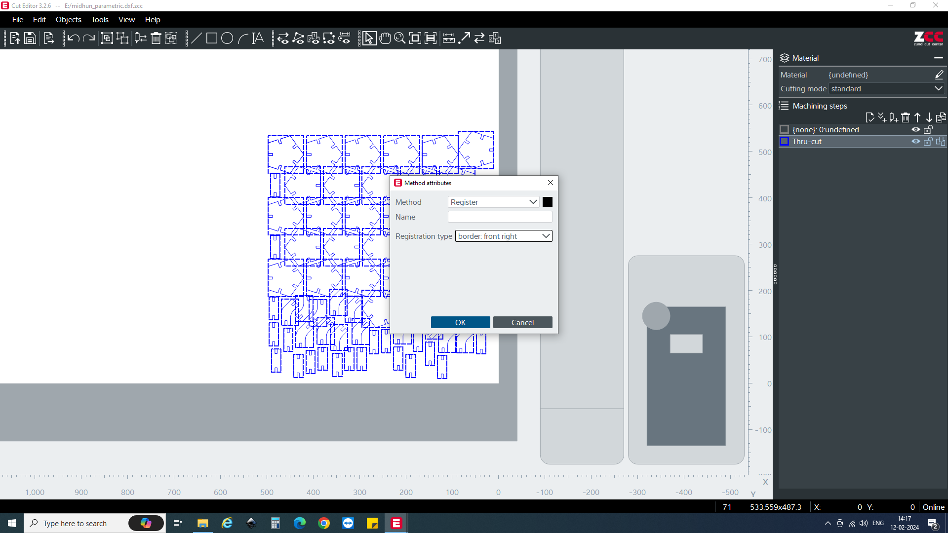
The machine is equipped with a scanner that automatically scans the bed and locates the corners of the inserted sheet. While this process can also be performed manually, creating a Job register isn't mandatory; however, it can significantly reduce manual effort. To implement this, add step by selecting "Register." Next, designate the position from which you want to commence cutting. To ensure the registration occurs prior to cutting, adjust the job position upwards using the arrow mark.
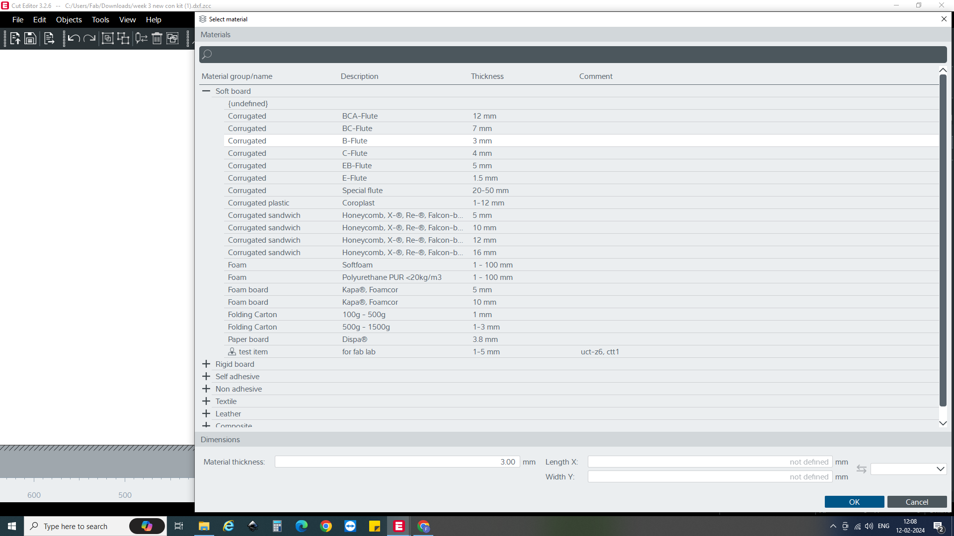
Once the operation type is chosen, proceed to select the material to be used for cutting. This option can typically be found in the right-hand corner of the interface. I chooseed “B-Flute of thickness 3mm”
Once these steps are completed within the cut editor, the work is finalized. At this point, the file is ready to be sent to the cut queue application for further processing.
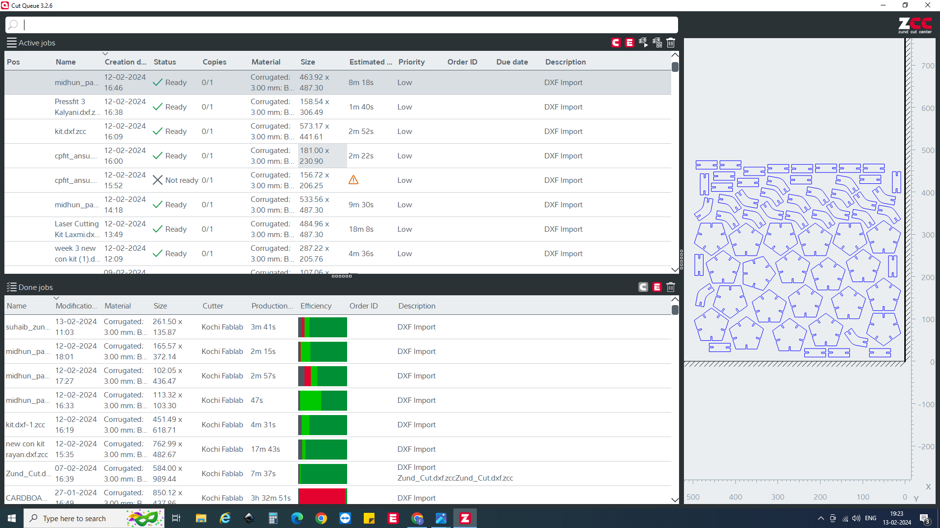
After double-clicking on the required file that needs processing, the Cut Center software will automatically launch, ready to begin the next stage of the workflow.
In the Cut Center software, select the required module and tool that you intend to use for the job. Before proceeding, double-check the bed clearance to ensure that the tool does not cut through the bed. This step is crucial for preventing damage to the equipment. Once verified, proceed with the cutting process.
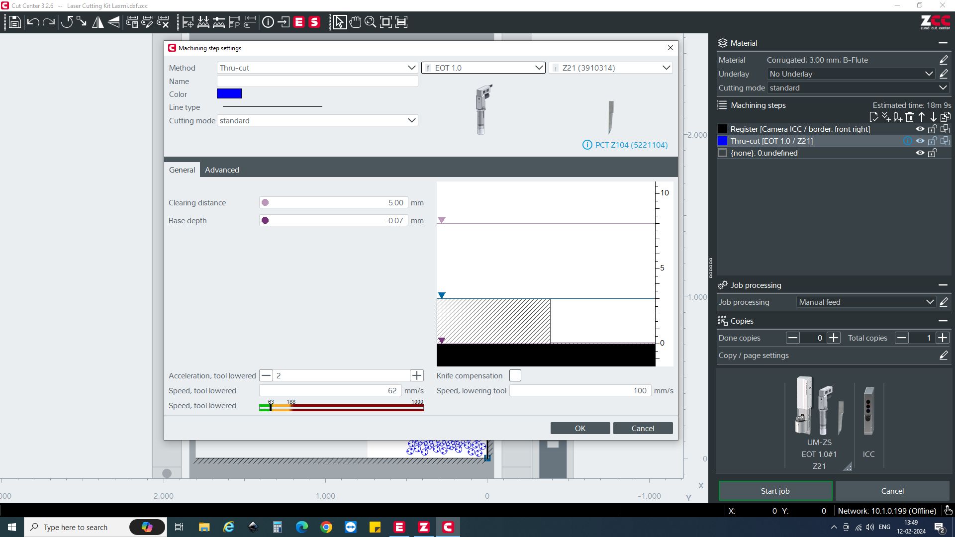
Following the tool and module selection, initiate the cutting process. At this stage, you'll be prompted to select the origin point. Since we previously designated the origin as front right, the software will automatically detect the edge based on this reference and commence the cutting process accordingly.
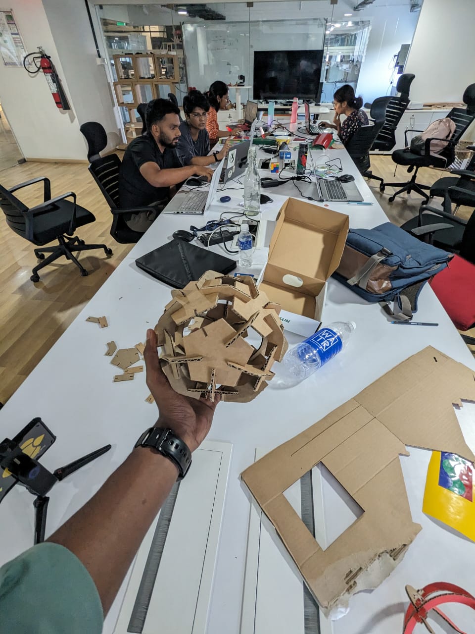
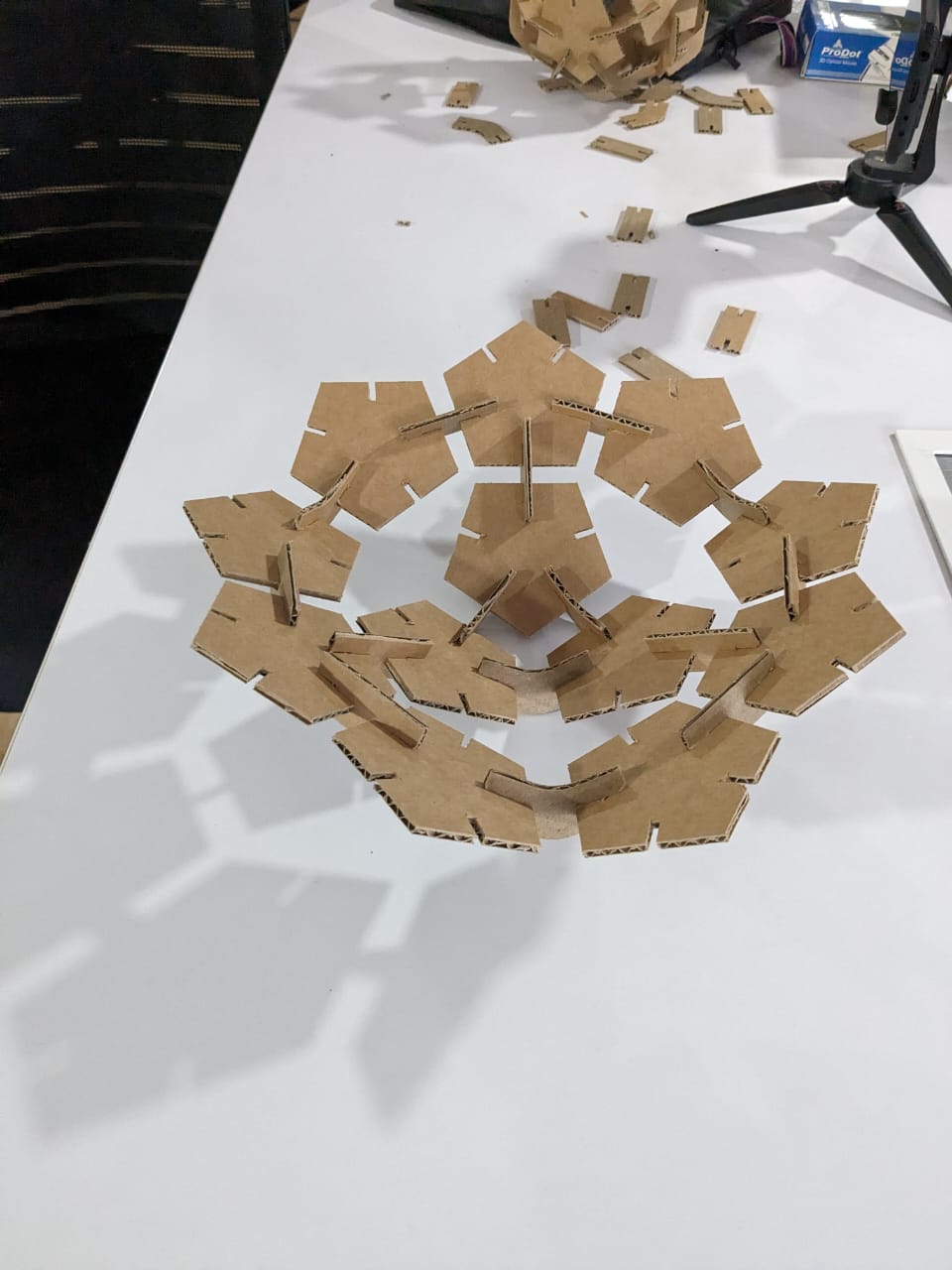
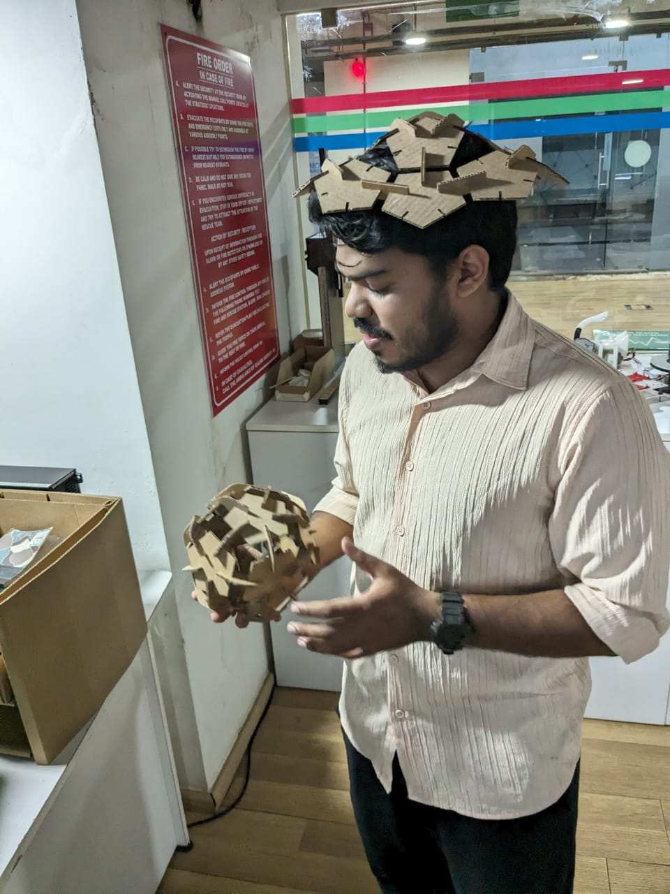
After completing the cutting process, I proceeded to construct various models using the parametric materials.
Here are some examples of the models I create